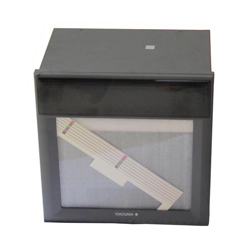
 YOKOGAWA µR10000/µR20000 Strip Chart Recorder
Intelligent Industrial Recorders
The YOKOGAWA µR series are the compact industrial recorders with the recording widths of 100 mm (µR10000) and 180 mm (µR20000).
YOKOGAWA µR10000: 1, 2, 3, 4-pen and 6-dot models
YOKOGAWA µR20000: 1, 2, 3, 4-pen and 6, 12, 18, 24-dot models
Model Codes:
��R10000:
YOKOGAWA 436101: µR10000 1 pen recorder
YOKOGAWA 436102: ��R10000 2 pen recorder
YOKOGAWA 436103: ��R10000 3 pen recorder
YOKOGAWA 436104: ��R10000 4 pen recorder
YOKOGAWA 436106: ��R10000 6 dot recorder
��R 20000:
YOKOGAWA 437101: ��R20000 1 pen recorder
YOKOGAWA 437102: ��R20000 2 pen recorder
YOKOGAWA 437103: ��R20000 3 pen recorder
YOKOGAWA 437104: ��R20000 4 pen recorder
YOKOGAWA 437106: ��R20000 6 dot recorder
YOKOGAWA 437112: ��R20000 12 dot recorder
YOKOGAWA 437118: ��R20000 18 dot recorder
YOKOGAWA 437124: ��R20000 24 dot recorder
Option:
/A1: Alarm output relay (2 contacts) 1
/A2: Alarm output relay (4 contacts) 1
/A3: Alarm output relay (6 contacts) 1, 2
/C3: RS-422A/485 communication interface 3
/C7: Ethernet communication interface 3
/F1: FAIL/chart end detection and output 2
/H2: Clamped input terminal 4
/H3: Non-glare door glass
/H5[ ]: Portable Type 7
/M1: Mathematical function
/N1: Cu10, Cu25 inputs
/N2: 3 legs Isolated RTD 4, 5
/N3: Expansion inputs 6
/P1: 24V DC/AC Power Supply 7
/R1: Remote control (5 contacts)
/CC1: Calibration Correction
RXA10-01: RXA10 configuration software Windows 2000/XP
RXA10-02: RXA10 configuration software (With interface unit), Windows 2000/XP
Input
_Measurement Inputs
��R10000: 1, 2, 3, 4 (pen) and 6 (dot) points
��R20000: 1, 2, 3, 4 (pen) and 6, 12, 18, 24 (dot) points
_Inputs
Universal input
DCV: 20, 60, 200 mV 2, 6, 20, 50 V, 1-5 V
TC: R, S, B, K, E, J, T, N, W, L, U, WRe
RTD: Pt100, JPt100
DI: Digital Input (contact or DC Voltage, TTL level).
DCA: Direct Current Input (using external shunt resistor (10 ��, 100 ��, 250 ��) )
_Measurement Interval
Pen model������125 ms/channel
Dot model������ ��R10000: 1 s/6 dot or 2.5 s/6 dot
��R20000: 1 s/6 dot, 2.5 s/12 to 24 dot or 2.5 s/6 dot, 5 s/12 dot, 10 s/18 to 24 dot
_Burnout
Available on TC and 1-5 VDC range, ON/OFF selectable (per channel)
1-5V Burnout: less than 0.2V
_Filter
Pen model: Signal damping
ON/OFF selectable (per channel), Time constant (2, 5, 10sec)
Dot model: Moving average
ON/OFF selectable (per channel), Moving average cycle (2 to 16)
_Standard Computation
Differential computation, Linear scaling, Square root, Bias addition
Recording and Printing
_Recoring Method
Pen model: Disposable felt pens, Plotter pen, Dot model: 6 color wire dot
_Pen Offset Compensation: ON / OFF selectable (Pen model only)
_Effective Recording Width
YOKOGAWA ��R10000: 100 mm, ��R20000: 180 mm
_Chart ��R10000: Plain-paper Z-fold chart (16 m)
YOKOGAWA ��R20000: Plain-paper Z-fold chart (20 m)
_Recording Period
Pen model: Continuous for each channel
Dot model: ��R10000; Max. 6 ch/10sec
��R20000; Max. 6 ch/10 s, 7 to 12 ch/15 s. 13 to 18 ch/20 s, 19 to 24/30 s
_Chart Speed
Pen model: 5 to 12000 mm/h (82 increments)
Dot model: 1 to 1500 mm/h (1 mm step)
_Chart Speed Change
speed 1, speed 2 change by remote control signals (option).
_Recording Colors
Pen model: pen1=red, pen2=green, pen3=blue, pen4=violet, plotter pen=purple
Dot model: ��R10000
ch1=purple, ch2=red, ch3=green, ch4=blue, ch5=brown,
ch6=black (color can be assigned to any channel)
��R20000
ch1, 7, 13, 19=purple ch2, 8, 14, 20=red ch3, 9, 15, 21=green
ch4, 10, 16, 22=blue ch5, 11, 17, 23=brown ch6, 12, 18,
24=black (color can be assigned to any channel)
_Recording Format
Analog recording: Zone recording, Partial expanded recording
Digital printout: Channel number or TAG (Dot model only), Alarm, Periodic printout or Report printout, Message printout, Record start time, Chart speed printout, List printout, Manual printout,
SET UP List printout
Display
_Display Method
��R10000: VFD (101_16 dot matrix), ��R20000: VFD (181_16 dot matrix)
_Display Types
Multiple displays
Digital, bar, flag, DI/DO display etc. can be displayed.
15 display types can be selected from approx. 80 display types.
_Status Display
Recording in progress (RECORD), Shared alarm (ALARM), Channel No.
display of occuring alarm (pen model: 1 2 3 4 or Dot model: ��R10000; 1 to 6, ��R20000; 1 to 24), Chart end display (CHART END) For the model with option (FAIL/chart end detection and output), Math (MATH), Key lock display (KEY LOCK)
_Setting
Settings display by interactive mode. In setting, navigator method is used.
Display updated interval can be selected from AUTO/MAN.
_Bar Gragh Display
Measurment value: left/right (%) reference or center zero reference display (each channel selectable).
Alarm: Alarm setting level display and flashing display of occuring alarm.
_Display Brightness Setting Display brightness level: 1 to 8
Alarm
_Number of Levels: Up to 4 level for each channel.
_Alarm Type
High and low limits, differential high and low limits, high and low- rate of change limits and delay high and low Interval time of rate-of-change alarms:
The measurement interval times 1 to 15
_Display
Set value is indicated as a point on the bar gragh (only for bar gragh display)
In case of an alarm: - For digital display: Alarm type indicator
- Shared alarm display
- Alarm occuring channel No. is displayed
- For bar gragh display: Flashing point indicator
Power supply
_Rated Power Voltage: 100-240 VAC (automatically selected)
_Power Voltage Range: 90-132 VAC, 180-264 VAC
_Rated Power Flequency: 50 Hz/60 Hz (sutomatically selected)
_Power Consumption
General Specification
_Ambient Temperature and Humidity
0 to 50��C, 20 -80%RH (at 5 to 40��C)
_Memory Backup
Litium battery to save settings parameters
Approx. 10 years (at room temperature, for standard model)
_Settings Protection Function
Password method
_Internal Light
White LED
_Operation Position
0�� Frontwards: Within 30�� from horizontal
Optional Specification
_Alarm output relay (/A1, /A2, /A3, /A4*, /A5*)
Number of output: 2, 4, 6, 12*, 14*
Relay contact rating: 250 VDC/0.1 A (resistance load), 250 VAC (50/60 Hz) /3 A
*only for ��R20000
_RS-422A/485 communication interface (/C3)
Measurment value output and setting parameter input/output
Conforms to EIA-422A (RS-422A) and EIA-485 (RS-485) standard
_Ethernet communication interface (/C7)
Measurment value output and setting parameter input/output
Transmission media:10 Base-T
Protocol: TCP, IP, UDP, ICMP, ARP
_FAIL/chart end detection and output (/F1)
In CPU error occurence or the chart end, output relay is activated.
Relay contact rating: 250 VDC/0.1 A (resistance load), 250 VAC (50/60 Hz) /3 A
_Clamped input terminal (/H2): Clamped input
_Non-glare door glass (/H3)
Non-glare door glass for front door
_Portable Type (/H5[ ])
Provides carrying handle and power code
_Mathematical function (/M1)
Number of computation channel: 8 channels (pen model), 12 channels (��R10000 dot model), 24 channels (��R20000 dot model)
Arithmetic operation (+, �C, ��, ��), Square, Absolute, Common logarithm (y=log10x), Exponential (eX), Power (Xn), Relational operator (<, ��, >, ��, =, ��), Logic (AND, OR, NOT, XOR)
Statistical computation: Statistical type: MAX, MIN, AVE, SUM, MAX-MIN
Comutation channel can be recorded
_Cu10, Cu25 RTD input (/N1)
Cu10, Cu25 RTD input
Pt100 and JPt100 inputs can be used together.
_3 legs isolated RTD input (/N2): A, B, b legs of RTD are isolated for dot model
_Expansion inputs (/N3)
Following input types can be supported besides standard inputs.
TC: PR40-20, PLATINEL, NiNiMo, W/WRe26, Type N (AWG14), Kp vs Au7Fe
RTD: Pt25, Pt50, Ni100 (SAMA), Ni100 (DIN), Ni120, J263*B, Cu53, Cu100
*Cu100 : ��=0.00425 at 0��C
_24V DC/AC Power Supply (/P1)
Rated power supply: 24 V DC/AC
Allowable power supply voltage range: 21.6 to 26.4 V DC/AC
Rated power supply frequency: 50/60 Hz
_Remote control (/R1)
Below actions can be assigned to up to 5 points
Recording start/stop, Chart speed change, Message printout start, Manual printout start, Alarm ACK, Time set, Math start/stop, Math reset
_Calibration Correction (/CC1)
Corrects the measurement value of each channel using segment linearizer approximation.
Number of segment points: 2 to 16